The original ETA-3400 used two 24 pin 2K ROMs for the Tiny BASIC and Fantom II monitor, up to eight 18 pin 1K x 4bit static RAMs for a maximum of 4K of RAM, a 6820 PIA for serial I/O to a terminal and cassette ports, and a 32 byte ROM programmed as a memory decoder. There is a single comparator chip used in the cassette port input. As well as that the unit had an on board power supply to supply regulated +5V, +12V and -12V supplies.
All this took up a fair amount of space and the PCB was around 8" x 8". Quite large for what you get. I want to have more ROM, perhaps 16K - 32K, and more RAM, 48K - 64K. If I was to use the same parts that the original ETA-3400 used it would be massive, I'd imagine larger than the old XT motherboards.
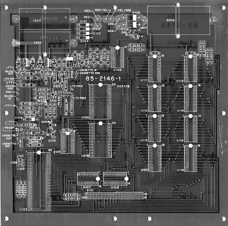
the original PCB layout
While it's certainly possible to use the same vintage parts, there are a few things that make it impractical. You would need 96 x 2114 RAM chips, and they are getting quite hard to find and also expensive. Having that many RAM chips would also draw a lot more power requiring a power upgrade. The ROMs are only 2K, so to get 16K you would need 8 of those (using 2716 EPROMs for example). The 6820 PIA is not easily replaced, and it's still relatively easy to obtain, and it's just one chip that does two or three functions. The 32 byte PROM decoder isn't something that can be purchased any more, and since it can't handle more than 8 outputs to select ROM, RAM, PIA etc, there isn't enough to control more memory using 1K x 4bit RAMs. The analogue circuit that drives the serial terminal and cassette ports is also taking up a big chunk of space.
What most modern ETA-3400 remakes do is use a single larger EPROM or EEPROM, 8K or larger, and a single static RAM chip 8K - 32K, the PIA and the comparator is maintained, the analog serial circuitry is replaced with a single RS232 chip with supporting components for voltage level translation, and the 32 byte decoder PROM is replaced with a programmable GAL.
That's roughly what I intend to do also. I'll use a single 128KB static RAM (628128), a single 32K EPROM (27C256), a 6821 PIA (same as 6820), a comparator chip (LM2901), and a 22V10 GAL for decoding memory. I want to maintain the analogue circuitry and Power Supply if possible, and squeeze it up a bit. Modern capacitors are a lot smaller than the ones used in the original ETA-3400. I also want to have options for the ROM, RAM and PSU sections so that different parts can be used on a single design. Jumpers or solder pads may be required to select different options.
Going with this plan I will only be using 5 x ICs. If the analogue circuitry ends up taking up too much room, I'll scrap it and go with what others have done with a modern RS232 chip. Although I've initially chosen a 22V10 GAL which is 24 pins, if I end up not using all of it, I will drop back to a slightly smaller 16V8 or 20V10 GAL, but for now having the larger chip won't restrict the programming.
I only started using GALs a year or two ago when I got a decent multi chip programmer. Although they are superseded by CPLDs and FPGAs somewhat, they can still be sourced relatively cheaply, and ATMEL still make the 22V10. They are commonly used as memory decoding chips which is how I will be using them here. The good thing about GALs are that they are re-programmable up to a certain number of times, typically 100 times. So if your first or second attempt doesn't work as expected you have plenty of attempts available.
The 22V10 GAL has 12 input pins and 10 output pins, although the output pins can also be programmed as input pins if more are needed. Internally it has a huge AND/OR/INVERTER array. Programming the device causes links to be made between certain intersections that create a logic circuit. Using the right circuit it is possible to make the GAL perform the function of a memory decoder. However to do this requires a .jed file to program the device. A .jed file is a table created for a specific GAL that a device programmer uses, and while it could be typed up manually it would be extremely difficult and would require a deep understanding of the encoding of the file. Instead what is normally done, is a program called WINCUPL (for Windows), or CUPL (for DOS), is used to compile a table of equations that you type up in a text editor.
Each equation is a text string that normally has certain input pins written as a logic equation resulting in a specific result that is assigned to an output pin.
I'll discuss how a basic WINCUPL equation is written next, and of course it uses different symbols than what you would expect...


No comments:
Post a Comment